Ray Tracing for the Movie ‘Cars’
Per H. Christensen Julian Fong David M. Laur Dana Batali
Pixar Animation Studios
编辑整理和翻译 : Happy_高兴

ABSTRACT
This paper describes how we extended Pixar’s RenderMan renderer with ray tracing abilities. In order to ray trace highly complex scenes we use multi-resolution geometry and texture caches, and use ray differentials to determine the appropriate resolution. With this method we are able to efficiently ray trace scenes with much more geometry and texture data than there is main memory. Movie quality rendering of scenes of such complexity had only previously been possible with pure scanline rendering algorithms. Adding ray tracing to the renderer enables many additional effects such as accurate reflections, detailed shadows, and ambient occlusion.
概要
这篇论文描述了怎样使用光线追踪的功能来拓展Pixar的RenderMan 渲染。为了使得复杂的场景的光线追踪效果更好,我们使用了多种分辨率的模型和材质缓存,还使用了光线微分来决定一个适合的分辨率。使用这种方法我们可以很高效的完成对有多个模型的场景和材质数据的光线追踪。对如此复杂的场景的电影级别的渲染,在之前只有使用纯扫描线渲染算法的可能性。将光线追踪添加到渲染器中可以得到很多精确的反射,更细腻的阴影和环境OCC。
The ray tracing functionality has been used in many recent movies, including Pixar’s latest movie ‘Cars’. This paper also describes some of the practical ray tracing issues from the production of ‘Cars’.
光线追踪功能已经被用在了很多最近的电影中,包括Pixar最近的电影“汽车总动员”。这篇论文也对这部电影中遇到的实际的光线追踪情况做一些描述。
1 INTRODUCTION
Pixar’s RenderMan renderer (PRMan) is a robust production renderer that is used for many CG movies and special effects [1]. PRMan uses the REYES scanline rendering algorithm [4]. About five years ago, at the request of our external customers, we started a project to add on-demand ray tracing to PRMan.
简介
皮克斯的RenderMan渲染器(PRMan)是一个功能完美的商业渲染器,被使用在了很多CG电影和特效中。PRMan使用REYES扫描线渲染算法。五年以前,因一个客户的要求,我们开始将光线追踪添加到了PRMan中。
At roughly the same time, John Lasseter and his team started working on ‘Cars’, a movie that would turn out to be an ideal testing ground and showcase for the ray tracing functionality. There were two main rendering challenges in making the movie. First, ‘Cars’ has scenes that are much more complex than past Pixar movies; for
example, wide desert landscapes with many sagebrush and thorn covered cacti, and a racing oval with 75,000 cars as spectators. Second, ray tracing effects such as correct reflections, shadows, and ambient occlusion were needed to get the desired artistic look. Ray tracing these very complex scenes in manageable time was quite a challenge.
同年,John Lasseter和他的团队也开始加入“汽车总动员”的电影制作中,这部电影或许是测试光线追踪功能的理想胚胎。这部电影中有两个主要的渲染挑战。首先,“汽车总动员”有比以往Pixar电影中更复杂的场景;例如,广袤的沙漠,有山艾树、仙人掌在其中,还有追踪观众席中75000个汽车模型。其次,光线追踪影响诸如正确的反射、阴影和环境OCC等等这些必要的因素来得到一个满意的视觉效果。在安排的时间里完成光线追踪复杂的场景确实是一个挑战。
The REYES algorithm is very efficient at handling complex scenes. For ray tracing, we use ray differentials [6, 14] to select the optimal tessellation level of surfaces and the proper MIP map level for textures. A multiresolution geometry cache keeps recently tessellated geometry ready for fast access. Similarly, a multiresolution texture cache keeps recently accessed texture tiles ready for fast access. This combination of ray differentials and caching makes ray tracing of very complex scenes feasible.
REYES算法在处理复杂的场景时非常高效。对于光线追踪,我们使用了光线微分来选择最佳细分程度的表面和适合的MIP材质贴图。
This paper first gives a more detailed motivation for the use of ray tracing in ‘Cars’, and lists the harsh rendering requirements in the movie industry. It then gives an overview of how the REYES algorithm deals with complex scenes and goes on to explain our work on efficient ray tracing of equally complex scenes. An explanation of our hybrid rendering approach, combining REYES with ray tracing, follows. Finally we measure the efficiency of our method on a test scene, and present a few production details from the use of ray tracing for ‘Cars’.
这篇论文首先介绍了光线追踪在“汽车总动员”中的具体目的,罗列了在电影制作中苛刻的渲染要求。然后介绍了REYES算法在处理复杂场景的大体理念,然后又介绍了我们在高效的完成光线追踪在复杂场景中的工作。然后叙述一下使用混合渲染方案:将REYES与光线追踪结合来渲染。最后,我们对一个测试场景进行了有效的处理,呈现了使用光线追踪得到的产品级细节。
Please refer to Christensen et al. [3] for an overview of previous work such as the Toro [10] and Kilauea [7] renderers. Recent related work includes an interactive out-of-core renderer by Wald et al. [15], the Razor project by Stoll et al. [13], and level of detail representations for efficient ray tracing of simplified geometry [2, 18]. The focus of those projects is more on interactive or real-time rendering than on movie-quality images.
请参阅Christensen et al 对之前的渲染器Toro 和 Kilauea进行全面了解。最近相关的工作包括一个交互式的 out-of-core 渲染器,和使用光线追踪对简单模型的细腻呈现。这些工程的关注点更多的集中在了互动或者实时渲染上而不是电影级图片。
2 MOTIVATION: WHY RAY TRACING?
动机:为什么是光线追踪?
There are several reasons why the directors chose to use ray tracing for ‘Cars’: realistic reflections, sharp shadows, and ambient occlusion.
许多原因来解释为什么导演选择使用光线追踪:真实的反射、有锐度的阴影和环境OCC。
Real cars are usually shiny, and the reflections are an important visual cue to the shape and material of the car. With scanline algorithms such as REYES, reflections are usually computed using environment maps. However, this approach breaks down when the reflected points are close to the reflecting points, or if the reflected points are also reflectors. Figure 1 shows two early pre-production test images of Luigi, a yellow Fiat 500 “Topolino”. The images compare environment mapping with ray traced reflections. While the environment map reflection in figure 1(left) shows a good approximation of the distant environment, it does not capture interreflections such as the reflections of the eyes in the hood seen in figure 1(right).
真实的汽车通常都是闪耀的,反射在对车的形体和材质上是一个重要的视觉因素。使用扫描线算法,例如REYES,反射通常使用环境贴图来计算得到。然而,这种方法在当被反射点离反射的点太近时,或者如果被反射的点也是反射体时彻底崩溃。图1是两幅测试图片,环境贴图与光线追踪的对比。左图是环境贴图反射,展示了一个与周围环境恰到好处的反射效果,它没有计算汽车上眼睛反射到车身的相互反射,右图。
Shadows give strong cues about the lighting and about the placement of objects relative to each other. Scanline algorithms traditionally compute shadows using shadow maps [11], and there are still many cases where a shadow map is the most efficient way of generating high-quality shadows. However, some of the scenes in ‘Cars’ use expansive sets but also have a lot of tiny, detailed geometry. This can lead to resolution problems in shadow maps. Furthermore, many scenes contain thousands of light sources, so keeping track of the shadow map files can
become an asset management problem. Figure 2 shows a frame from the final movie with Lightning McQueen leading a race. This is an example of a large scene requiring very fine shadow detail. The scene contains nearly 1000 light sources. Using ray traced shadows eliminates the resolution and asset management problems.
阴影给了灯光、多个物体之间相互影响等以足够的说服力。扫描线算法传统的处理方式是使用阴影贴图来计算阴影,这种方法在多种情况下依旧是一种得到高质量阴影最有效的方案。然而,在“汽车总动员”中的有些场景设定非常恢弘,而且有许多很小的有细节的模型。这样就会导致阴影贴图的分辨率问题。更严重的是,很多场景包括上千个灯源,因此处理阴影贴图文件将会非常难以管理。图2是最终的产品级渲染。这张图是一个大场景中有很好的阴影细节的展示。这个场景包含将近1000盏灯源。使用光线追踪阴影解决了刚才提到的问题。
Another use of ray tracing is for ambient occlusion. Ambient occlusion [9, 19] is a measure of how much light reaches a point from a uniformly lit hemisphere. Ambient occlusion is widely used in movie production since it gives a good indication of creases on surfaces and spatial proximity of objects, and is a cheap (but crude) approximation of global illumination. Figure 3 shows ambient occlusion on three cars in Radiator Springs. Ambient occlusion is usually computed by shooting many rays to sample the coverage of the hemisphere above each point.
光线追踪的另一个使用方面是环境OCC。环境OCC是一个测量有多少盏灯从由统一的被灯光照射的半球到达一个点的。光线OCC被广泛使用在电影产品中,因为它在处理表面接缝和一个物体的空间关系方面表现非常好,而且在得到近似全局光方面非常便宜(但是非常粗糙)。图3展示了环境OCC在三辆车间的渲染。环境OCC通常是通过计算 发射多条射线来采样覆盖在每个点上的半球来得到的。
3 MOVIE RENDERING REQUIREMENTS
3 电影渲染的要求
The rendering requirements in the movie industry are extremely
harsh:
• Scene geometry is far too large to fit in memory in tessellated form.
• Many surfaces are displacement-mapped.
• There may be thousands of textures (too many to fit all in memory at full resolution) to control reflection
parameters and displacements.
• There can be thousands of light sources.
• All illumination and surface reflection characteristics are controlled by fully programmable, complex
shaders.
In addition, images are typically rendered at high resolution with motion blur and depth of field. Furthermore, no spatial or temporal aliasing is acceptable: no staircase effects, “crawlies”, popping, etc.
渲染要求在电影工业中是非常苛刻的:
·场景模型太大而不能匹配镶嵌的形态;
·许多表面都是使用置换贴图;
·成千上万的贴图文件控制反射参数和置换;
·成千上万个灯源;
·所有的照明和表面反射都是由通过编程的、复杂的材质球控制的。
除此之外,图片都是使用高分辨率渲染,并且带有运动模糊和景深。此外,没有空间或时间混淆现象可以被接受:没有阶梯效应,表面不均匀、跳等等。
4 REYES RENDERING OF COMPLEX SCENES
4 复杂场景使用REYES渲染
The REYES algorithm has many desirable properties such as coherent shader execution, coherent access to geometry and texture data, simple differential calculations, efficient displacement, fast motion blur and depth-of-field, and the ability to render very complex scenes.
REYES算法有许多优秀的属性,例如:连贯材质球的执行、连贯的介入模型和材质数据、简单微分计算、高效置换、快速运动模糊和景深,并且有渲染复杂场景的能力。
The REYES algorithm divides each surface into smaller patches, and each patch is tessellated into a regular grid of tiny quadrilaterals (aka. micropolygons). The small patches are easy to place into one (or a few) image tiles. A patch can be thrown away if it is entirely behind other opaque patches.
REYES算法将每个面分成多个小片,每个小片被镶嵌到一个规则的微小的四边形网格中。这些小片很容易放在一张图片板块中。一个小片可以被忽略如果它被其他不透明的小片挡住。
Shading is done at the vertices of the grid. Shading an entire grid at a time is advantageous for data coherency and differential calculations as needed for e.g. texture filter sizes. The shading rate is decoupled from visibility calculations: there is typically only one shading point (grid vertex) per pixel on average, while the pixel sampling rate typically is 4×4 for static images and even higher for images with motion blur.
贴图被赋在每个网格的顶点上。在同一时间将贴图赋给整个网格是保持数据连续性的一个优势,微分计算也是必要的,比如材质过滤值等。贴图速度从可视化计算中被减弱:通常每像素上平均只有一个渲染点,像素采样率通常是4 * 4对于静态图片来说,如果加上运动模糊的话会更高。
The REYES algorithm is very good at handling complex scenes. First, it can completely ignore all objects outside the viewing frustum. Second, it renders only one small image tile (typically 16×16 or 32×32 pixels) at a time. This means that the computation only needs a small fraction of the scene geometry and textures at any
given time. This maximizes geometry coherency and minimizes the number of tessellated surfaces that need to be kept in memory at the same time. Furthermore, as soon as a surface has been rendered, its data can be removed from memory since they will no longer be needed. Surfaces are divided and tessellated according to their size
on screen, so large distant surfaces automatically get a coarse representation. Likewise, distant objects only need coarse textures, so only coarse levels in the texture MIP maps will be accessed for those objects. For all these reasons, REYES deals gracefully with very complex geometry and huge amounts of texture.
REYES算法很善于处理复杂场景。首先,它可以完全忽略所有物体外部的可视平截体。其次,它同时可以渲染16*16 或者32*32的图片像素。这意味着计算只需场景模型和材质中一个小的碎片。这个最大化的连续性模型和最小化的表面分段数需要同时被载入到内存中。此外,一旦表面被渲染了,它的数据就会从内存中被清除,因为我们已经不需要它了。物体表面根据在镜头中的大小被分割成小块。因此远处的表面会自动被处理成粗糙的展现。同样的,远处的模型只需要一个粗糙的材质,因此,只有粗糙级别的材质在材质库中才可被赋到这些远处的模型上。基于这些原因,REYES能够处理大型的复杂的场景。
5 RAY TRACING OF COMPLEX SCENES
5. 光线追踪处理复杂场景
Ray tracing also has several wonderful properties as a rendering algorithm: it is conceptually simple, its run-time only grows logarithmically with scene complexity, and it can easily be parallelized. But ray tracing has an important limitation: it is only efficient if the scene fits in memory. If the scene does not fit in memory, virtual memory thrashing slows the rendering down by orders of magnitude.
光线追踪作为一个渲染算法拥有很多非常好的属性:它的理念很简单,它的运行时间只有在复杂场景中增长,很容易被并行化。但是它有一个重要的局限性:只有能够在内存中的场景可以高效使用。如果场景没有被放在内存中,虚拟内存将会使得渲染非常的慢。
Ray tracing of complex scenes is inherently harder than REYES rendering of similar scenes. First, objects can’t be rejected just because they are outside the viewing frustum: they may cast shadows on visible objects or be reflected by them. Second, even if the image is rendered one tile at a time and the directly visible geometry is
ray traced very coherently, the reflection and shadow rays will access other geometry (and textures) in a less coherent manner. Even worse, the rays traced for diffuse interreflections and ambient occlusion are completely incoherent and may access any part of the scene at any time. Hence, we can’t delete an object even when the image tile it is directly visible in has been rendered — a ray from some other part of the scene may hit that object at any time during rendering.
光线追踪复杂的场景与生俱来的比REYES难很多。首先,能够被看见的物体不能被忽略:他们或许投射阴影到可视的物体上或者互相发射。其次,尽管图片在同一时间被渲染,可视的物体连续的被光线追踪,反射和阴影射线将会不连续的进入其他的物体中。更糟糕的是,对于漫反射互相发射和环境OCC的光线追踪是完全不连续的,而且可能在任何时间进入场景中的任何地方。因此,我们不能删除一个物体,从场景中任何一个地方的射线都可以在任何渲染时间中碰到那个物体上。
For all the reasons listed above, ray tracing of very complex scenes may seem like a daunting task. However, the use of ray differentials and multi resolution geometry and texture caches makes it tractable.
对于上面提到的那么多因素,光线追踪对复杂场景来说看起来有点不能胜任。但是,光线微积分的使用和多分辨率模型(多级细分曲面)和材质缓存使得它变得可行。
5.1 Ray differentials
5.1 光线微积分
A ray differential describes the differences between a ray and its — real or imaginary — “neighbor” rays. Igehy’s ray differential method [6] traces single rays, but keeps track of the differentials as the rays are propagated and reflected. The differentials give an indication of the beam size that each ray represents, as illustrated in figure 4. The curvature at surface intersection points determines how the ray differentials and their associated beams change after specular reflection and refraction. For example, if a ray hits a highly curved, convex surface, the specularly reflected ray will have a large differential (representing highly diverging neighbor rays).
一个光线微积分描述一条射线和它周围的射线之间的区别。Igehy的光线微积分方案追踪单个光线,但是保持光线被发射并且反弹回来的微积分射线轨迹。微积分指出每个光线呈现的光柱的大小,如图4.表面交叉点的曲率决定了光线微积分和与其像连接的光柱在镜面反射和折射后是怎样变化的。例如,一束光线碰到弯曲隆起的表面时,镜面反射光线将会有一个很大的微积分(表现出高度分离的相邻的光线)。
Suykens andWillems [14] generalized ray differentials to glossy and diffuse reflections. For distribution ray tracing of diffuse reflection or ambient occlusion, the ray differential corresponds to a fraction of the hemisphere. The more rays are traced from the same point, the smaller the subtended hemisphere fraction becomes. If the hemisphere fraction is very small, a curvature-dependent differential (as for specular reflection) becomes dominant.
Suykens 和 Willems归纳了光线微积分在镜面反射和漫反射上的作用。对于漫反射和环境OCC的光线追踪分布,光线微积分回应从半球上的小部分上反弹回来的信息。越多的光线从一个相同的点被追踪,相对的半球部分会变得更小。如果半球部分变小了,一个依靠曲率的微积分会越有支配地位。
In Christensen et al. [3] we provided a comprehensive analysis of ray differentials vs. ray coherency. We observed that in all practical cases, coherent rays have narrow beams and incoherent rays have wide beams. This is an important and very fortunate relationship that enables ray tracing of very complex scenes. We exploit that relationship in the following sections by designing caches that utilize it.
在Christensen et al.中,我们对 光线微积分VS光线连续性 做了一个全面的分析。我们观察到,在所有的实际项目中,连续的光线是非常细的光柱,不连续的光线是宽的光柱。这是一个非常重要的并且非常幸运的关联,能够使得光线追踪更加复杂的场景。在之后的制作部分中我们通过设置缓存等拓展了这个相关性。
5.2 Multi resolution tessellation
5.2 多分辨率网格布线
REYES chooses tessellation rates for a surface patch depending on viewing distance, surface curvature, and optionally also view angle. In our implementation, the highest tessellation rate used for ray tracing of a patch is the same as the REYES tessellation rate for that patch. Subsets of the vertices are used for coarser tessellations, which ensures that the bounding boxes are consistent: a (tight) bounding box of the finest tessellation is also a bounding
box for the coarser tessellations. The coarsest tessellation is simply the four corners of the patch. One can think of the various levels of tessellation as a MIP map of tessellated geometry [17]. Figure 5 shows an example of five tessellations of a surface patch; here, the finest tessellation rate is 14×11.
REYES选择一个表面的网格分布密度是根据镜头与表面的距离、表面曲率和摄像机的观看角度。在我们的执行中,使用最高密度的网格来对一个片进行光线追踪与REYES片的网格密度是一样的。顶点的子集应用在有接缝的网格中,这样就保证线框显示是连续的:一个精细化的线框显示也是一个有粗糙的网格分布。最粗糙的网格布线是有四个角的片。你可以想象不同级别的网格布线作为网格布线几何体的一个MIP贴图。图5展示了不同级别的网格布线。
In our first implementation [3], the tessellation rates used for ray tracing were 16×16, 8×8, . . . , 1. However, using the REYES tessellation rates and subsets thereof has two advantages: there are fewer quads to test for ray intersection (since we always rounded the REYES tessellations rates up for ray tracing), and there are fewer self-intersection problems if we use a hybrid rendering method (since the vertices of the two representations always coincide when using the current tessellation approach).
在我们的第一步执行中,光线追踪使用的网格密度是16*16,8*8 … 然而,使用REYES网格分布密度和它的子集可以有两个优势:有很少的四边形被用来做光线交互,如果我们使用混合渲染方案,将会有很小的自反射问题出现。
The example in figure 5 is a rectangular surface patch. We have a similar multi resolution tessellation method for triangular patches which arise from triangle meshes and Loop subdivision surfaces.
图5是一个规则的四边面片。我们也有相似的三角形的面片,从这些面片和细分面片中截取三角形片。
5.3 Multiresolution geometry cache
5.3 多分辨率物体缓存
We tessellate surface patches on demand and cache the tessellations. As shown above, we use up to five different levels of tessellation for each surface patch. However, we have chosen not to have five geometry caches; instead we use three caches and create the two intermediate tessellations by picking (roughly) a quarter of the vertices from the next finer tessellation level.
我们根据需求来分布网格并且给这些网格做缓存。就像上面提到的,我们给每个模型使用最多五种不同的网格密度。然而,我们没有为这五种网格密度都做缓存,取而代之,我们使用三种缓存,并且从下一个高密度网格的点上选择四分之一的点来创建两个中间的网格分布。
In our implementation, the coarse cache contains tessellations with 4 vertices (1 quad), the medium cache contains tessellations with at most 25 vertices, and the fine cache contains all larger tessellations (at most 289 vertices). The size of the geometry caches can be specified by the user. By default, the size is 20MB per thread allocated for each of the three caches. Since the size of the tessellations differ so much, the maximum capacity (number of slots) of the coarse cache is much higher than for the medium cache, and the medium cache has much higher capacity than the fine cache. We use a least-recently-used (LRU) cache replacement scheme.
在我们的操作中,低模的缓存包括有四个点的网格分布,也就是一个四边形,中模的缓存有25个点构成的网格,高模的缓存有多达289个点的高精度网格分布。物体缓存的大小由用户来选择。默认情况下,为这三个缓存每个线程分别分配20MB。由于网格密度的区别很大,低模的最大存储比中模的缓存要大很多,中模的最大存储比高模的大很多。我们使用最近用到的缓存最少的数据来代替表格。
For ray intersection tests, we choose the tessellation where the quads are approximately the same size as the ray beam cross section. We have observed that accesses to the fine and medium caches are usually very coherent. The accesses to the coarse cache are rather incoherent, but the capacity of that cache is large and its tessellations are fast to recompute.
对于光线反弹测试,我们选择四边形的网格与光柱穿梭其中的数据大小相同的网格模型。我们发现当光线进入中模和高模缓存时都是连续的,但是进入低模时是完全不连续的,但是缓存的容量很大,重新计算网格模型时很快。
5.4 Multiresolution texture cache
5.4多分辨率材质缓存
Textures are stored on disk as tiled MIP maps with 32×32 pixels in each tile. The size of the texture cache is chosen by the user; the default size is 10 MB per thread.
存在硬盘上的材质都是MIP模式的贴图,每个贴图都是由32*32像素的小方格拼接成的。材质缓存的大小由用户选择,默认是每线程10MB。
As with the geometry cache, the ray beam size is used to select the appropriate texture MIP map level for texture lookups. We choose the level where the texture pixels are approximately the same size as the ray beam cross-section. Incoherent texture lookups have wide ray beams, so coarse MIP map levels will be chosen. The
finer MIP map levels will only be accessed by rays with narrow ray beams; fortunately those rays are coherent so the resulting texture cache lookups will be coherent as well.
对于物体缓存,光柱大小用来选择适合的MIP贴图精度。我们选择材质像素与光柱穿梭进模型时的大小相同的MIP材质。不连续的材质对应宽的光柱,因此低精度的MIP贴图将会被选中。高精度的MIP贴图将会被窄的光柱选中。幸运的是这些光线都是连续的,因此材质缓存的查找也会是连续的。
6 OTHER RAY-TRACING IMPLEMENTATION ISSUES
6. 其他的光线追踪操作遇到的情况
This section describes other efficiency and accuracy aspects of our implementation of ray tracing in PRMan.
这部分讲述在PRMan的光线追踪在其他操作方面的高效、精确的因素
6.1 Spatial acceleration data structure
6.1空间加速数据结构
Good spatial acceleration structures are essential for efficient ray tracing. We use a bounding volume hierarchy, the Kay-Kajiya tree [8]. This data structure is a good compromise between memory overhead, construction speed, and ray traversal speed. The data structure is built dynamically during rendering. While we are quite satisfied with the performance of the Kay-Kajiya tree, it is certainly worth considering other acceleration data structures in the future.
好的空间加速数据结构对光线追踪是非常有效的。我们使用一个框架体积层次,Kay-Kajiya树。这个数据结构能够在内存溢出、构建速度、光线往返速度方面得到一个平衡。
There is one more level of bounding volumes for the finest tessellations: bounding boxes for groups of (up to) 4×4 quads. These bounding boxes are stored in the fine geometry cache along with the tessellated points.
高一级的框架体积是专门为高精度模型的:这些是4*4的网格构成的。这些框架方格被存储在高精度模型缓存中。
6.2 Displacement-mapped surfaces
6.2使用置换贴图的表面
Displacement shaders complicate the calculation of ray intersections. If the surface has a displacement shader, the shader is evaluated at the tessellation vertices to get the displaced tessellation. The bounding box of the displaced vertices is computed, and the Kay-Kajiya tree is updated with the new bounding box.
置换材质球使得光线交互计算变得复杂。如果一个表面有一个置换材质球,这个材质球通过网格上的点来得到置换后的网格。被置换后的框架方块上的点也被计算,Kay-Kajiya树会根据新的框架方块自动更新。
Although there exist techniques for direct ray tracing of displaced surfaces [12], we have found that applying displacement shaders to tessellated grids gives much faster rendering times — at least if the displaced tessellations are cached.
尽管对置换后的表面的光线追踪存在着技术,我们发现将置换材质球赋给网格模型得到了更快的渲染时间。—-至少在给置换网格做缓存的前提下。
Each object that has displacement must have a pre-specified upper bound on the displacement; such bounds are important for the efficiency of both REYES rendering and ray tracing. Without a priori bounds, any surface might end up anywhere in the scene after displacement, and this makes image tiling or building an acceleration data structure futile.
每个物体需要置换的条件是必须有一个预先设定好的置换上限。这个上限对REYES渲染和光线追踪在高效性方面都是很重要的。 没有一个适合的上限,任何表面在置换后都有可能在场景的任何地方玩完,这将导致图片不能正确渲染。
The value of tight bounding boxes is so high that even if the first access to a displaced surface patch only needs a coarse tessellation, we compute a fine tessellation, run the displacement shader, compute the tight bounding box, update the Kay-Kajiya tree, and throw away those tessellation points that aren’t needed. This is a one-time
cost that is amortized by the reduction in the number of rays that later have to be intersection-tested against that surface patch. Tight bounding boxes allow us to ray trace displaced surfaces rather efficiently.
高精度的框架方块的值太高了以至于尽管当光线第一次进入一个置换的模型表面时只需要一个低模,我们计算一个高精度模型,运行置换材质球时,计算高精度框架方块,更新Kay-Kajiya树,丢掉不需要的网格点。这是以前一个通过减少光线的数量来降低成本的方法,然后测试光线与表面间的交互。高精度框架方块允许我们使用光线追踪来更有效的处理置换表面。
6.3 Motion blur
6.4 运动模糊
PRMan assumes that all motion is piecewise linear. There is a tessellation for the start of each motion segment plus a tessellation for the end of the last segment. These tessellations are computed on demand and stored in the geometry cache. For ray intersection tests, the tessellated vertex positions are interpolated according to the ray
time, creating a grid at the correct time for the ray.
PRMan假设所有的运动都是分段线性的。每个运动段的开始都有一个网格加上每个运动段的最后一个网格。这些网格都根据要求来计算,并且存储到物体缓存中。对于光线交互测试,这些网格点的位置根据光线的时间进行差值,为光线在正确的时间创建一个网格。
The Kay-Kajiya node for a moving surface patch contains a bounding box for the start of each motion segment plus a bounding box for the end of the last segment. The bounding boxes are linearly interpolated to find the bounding box that corresponds to the ray time.
对于一个运动的表面方块的Kay-Kajiya节点包括一个为每个运动段的开始而带的框架方块加上每个运动段结束时带的框架方块。框架方块通过线性差值来找到与光线交互的框架方块。
6.4 SIMD speedups
6.4 SIMD加速
We use SIMD instructions (SSE and AltiVec) to speed up the computation of ray intersections. When intersection-testing a Kay- Kajiya node bounding box, we test multiple slabs (x, y, and z planes) at once. The bounding boxes for groups of 4×4 quads of finely tessellated patches (stored in the fine geometry cache) are
intersection-tested four boxes at a time. And tessellated patches are intersection-tested 4 triangles (2 quads) at a time.
我们通过SIMD结构来加速光线互相交互的计算。当交互测试一个Kay-Kajiya节点的框架方块时,我们同时测试多个截面。对于4*4的高精度的多网格框架方块,四个盒子在同一时间被交互测试。网格方片在同一时间测试4个三角形,也就是两个正方形。
Since each ray is traced independently, our SIMD speedups do not rely on ray coherency. In contrast, Wald et al. [16] used SIMD instructions for tracing four rays at a time. This works fine if the rays are coherent, but fails to deliver a speedup if the rays are incoherent.
由于每个光线都是单独被追踪,我们的SIMD加速器没有依赖光线连续性。作为对比,Wald et al. 使用SIMD结构同时追踪4个光线。这项工作对于连续的光线是非常好的,但是对于不连续的光线传递加速却失败了。
6.5 Shading at ray hit points
6.5 给光线碰撞的点加材质
To compute the shading results at ray hit points, we could shade the vertices of ray tracing tessellations, store the colors in a cache, and interpolate the colors at the hit points. This would be a straighforward generalization of the REYES shading approach. But unfortunately the shading colors are usually view-dependent — highlights
move around depending on the viewing direction, for example. The shader may also compute different results depending on the ray level for non-realistic, artistic effects.
计算光线碰撞的点的材质,我们可以给通过光线追踪到的点赋材质,将颜色信息存储到一个缓存中,在碰撞点给颜色信息插值。这将是一个非常简单的REYES材质方法。但不幸的是,颜色信息都被分散了—-根据视觉方向,高光到处都是。材质球也会根据光线也会计算出不同的结果用以满足非写实的艺术的效果。
Instead we create 3 shading points for each ray hit (similar to Gritz and Hahn [5]). One shading point is the ray hit point, and the other two shading points are created using the ray differentials at the ray hit point. This way, the shader can get meaningful differentials for texture filtering, computation of new ray directions, etc. While
most shading functions are executed on all three shading points, some are only executed at the ray hit point—for example, rays are only traced from the ray hit point.
我们为每一个光线碰撞创建了三个材质贴图点。一个材质点是光线碰撞点,另外两个是在光线碰撞点上使用光线微积分来创建的。使用这种方法,材质球为材质过滤提供更多更有意义的微积分算法、新的光线方向的计算等等。当所有的材质函数都在这三个材质点上执行时,有些就只是在光线碰撞点上执行—例如,光线只在光线碰撞点上被追踪。
It is worth emphasizing that for production scenes, the dominant cost of ray tracing is typically not the computation of ray intersections, but the evaluation of displacement, surface, and light source shaders at the ray hit points. (This is also why ambient occlusion has gained popularity in movie production so quickly as an alternative
to more accurate global illumination solutions: even though it takes a lot of rays to compute ambient occlusion accurately, there are no shader evaluations at the ray hit points.)
我们有必要强调一下产品级场景的情况,光线追踪的主要花费通常不是光线交互的计算,而是置换、表面、灯光材质球在光线碰撞点上的计算。(这也是环境OCC作为更加精确的与全局光交互的解决方案迅速在电影级产品中流行的原因,尽管花费很多光线来使得计算环境OCC更加准确,但并没在光线碰撞点上计算材质球的值。)
6.6 Avoiding cracks
6.6 避免破面
Visible cracks can occur if the two grids sharing an edge have different tessellation rates. See figure 6 for an illustration. This is a potential problem both for REYES rendering and for ray tracing, and has to be dealt with explicitly.
如果两个网格面共同使用一个边的话,在不同布线密度下网格会产生明显的破面。图6. 这对于REYES渲染和光线追踪都是潜在的问题,必须明确的处理这个问题。
The easiest way to fix these cracks requires that all dicing rates are powers of 2. Then every other vertex on the fine tessellation side of the edge can be moved to lie along the straight line between its two neighbor points. This ensures that the vertices on both sides of the edge are consistent so there are no cracks. However, such power-of-two tessellation (aka. “binary dicing”) introduces too many shading points compared to more flexible tessellation rates, and it is therefore too expensive in practice when shaders are a bottleneck.
处理破面的最简单的方法是要求所有的方块分布频率是二次幂。然后其它的在高模边上的点就可以沿着两个相邻的点进行移动来成为一条直线。这样确保了线两边的点都是一致的,因此就可以修补破面了。然而,这种二次幂的布线方法与更加便利的布线密度相比,导致了更多的材质点,因而在实践中将会是一个瓶颈,导致花费过高而且不实际。
Instead, PRMan uses an alternative algorithm that glues all edges together [1, sec. 6.5.2], thus avoiding cracks. We call this algorithm “stitching”. Stitching moves the tessellation points so that the grids overlap, and introduces new quads if needed to fill remaining gaps. For REYES rendering, new quads that are introduced are never shaded, they only copy colors from their nearest neighbor.
取而代之,PRMan使用了一个可选择的算法来使得所有的线都缝合,这样就避免了破面。我们叫这种算法为“缝合”。缝合算法移动网格上的点因此这些网格交叠在一起,并且根据要求生成新的方格来填充裂缝。对于REYES渲染,新生成的四边形网格是不会被赋材质的,他们只是从周围的片上来复制颜色。
We use a similar stitching algorithm for ray tracing. If any new quads are generated, they are stored in the geometry cache.
我们对光线追踪使用相似的缝合算法。如果有新的四边形生成了,他们会被存储到物体缓存中。
The tessellation rate of each surface patch is determined from the size of the patch bounding box relative to the ray beam size. Hence, the tessellation within a patch is kept consistent for each ray, and there are no cracks internally within a patch. (Such cracks are sometimes refered to as “tunnelling” [13].)
每一个表面的布线密度是通过相对于光柱大小决定的框架方格的尺寸来决定的。因此,打到每个表面网格上的光线是保持一致的,并且每个片上没有破面。
7 HYBRID RENDERING: REYES AND RAYS
7 混合渲染:REYES 和光线追踪
PRMan uses a combination of the REYES algorithm and on demand ray tracing. REYES is used to render objects that are directly visible to the camera. Shading those objects can cause rays to be traced. With this hybrid approach there are no camera rays; all the first-level rays originate from REYES shading points.
PRMan使用REYE算法和光线追踪混合渲染。REYES用来渲染可以被摄像机直接看到的模型。给这些物体赋材质可以使得光线被追踪。使用混合方案没有从摄像机发射的光线,所有的第一层光线都是从REYES材质点上发射出来的。
With the methods described above, both the REYES and ray tracing algorithms can handle very complex scenes. So why not use ray tracing for primary rendering? It would unify our algorithm, eliminate large parts of the PRMan code base, and make software maintenance easier. However, so far the advantages of coherency, well defined differentials, graceful handling of displacement mapping, efficient motion blur and depth-of-field, decoupling of shading rate and pixel sample rate, etc. makes the REYES algorithm hard to beat for movie-quality rendering.
通过上面提供的法案,REYES和光线追踪算法都可以处理非常复杂的场景。因此为什么使用光线追踪作为首选渲染器呢?它可以统一我们的算法,简化PRMan中的大部分代码,使得软件稳定性增强。然而,到目前为止,一致性的优点是可以更好的定义微积分、更便捷的处理置换贴图,高效的运动模糊和景深、减少贴图精度和像素采样频率等等,使得REYES算法很难达到电影级渲染质量。
8 TEST ON A COMPLEX SCENE
8 复杂场景的测试
Figure 7 shows a test example, a scene with 15 cars. The cars are explicitly copied, not instanced. Each car consists of 2155 NURBS patches, many of which have trim curves. The cars have ray-traced reflections (maximum reflection depth 4) and sharp shadows, while the ground is shaded with ray-traced ambient occlusion. This gives a mix of coherent and incoherent rays. The image resolution is 2048×1536 pixels.
图7展示了一个测试图片,有15辆车的场景。很明显这些车都是复制出来的,而不是替代的。每个车包含2155个NURBS面,其中还有整齐的切线。这些车有光线追踪的反射和锐利的阴影,地面被赋予光线追踪环境OCC材质。这些提供了连续性和不连续性光线的结合。这张图的尺寸是2048*1536像素。
During rendering the car surfaces are divided into 1.3 million surface patches, corresponding to 383 million vertices and 339 million quads (678 million triangles) at full tessellation. Storing all full tessellations would consume 4.6 GB. Instead, with multi resolution caching, the scene uses a total of 414 MB: Geometry cache sizes
are set to their default value (20 MB per cache per thread), a total of 120 MB. The Kay-Kajiya tree uses around 59 MB per thread. The top-level object descriptions use 126 MB plus 50 MB for trim curves.
在渲染过程中,汽车模型被分为一百三十万个片,相当于三亿八千三百万个点和三亿三千九百万个四边形。保存所有的网格信息需要4.6GB。相反,对于多分辨率缓存,场景使用414MB:物体缓存大小设定为初始值(每线程每个缓存20MB), 一共是120MB。Kay-Kajiya树每线程使用59MB。高精度物体在物体描述方面使用126MB加上50MB切线。
Rendering this image used 111 million diffuse rays, 37 million specular rays, and 26 million shadow rays. The rays cause 1.2 billion ray-triangle intersection tests. With multi resolution geometry caching, the render time is 106 minutes. The three geometry caches have a total of 675 million lookups and cache hit rates of 91.4%–95.2%. In contrast, if the ray differentials are ignored (the REYES tessellation rates are used for all ray intersection tests) and
no caching is done, the render time is 15 hours 45 minutes — almost 9 times slower.
渲染这张图片使用一亿一千一百万漫反射光线,三千七百万高光光线,两千六百万阴影光线。这些光线触发了一百二十亿三角面光线测试。对于多种物体缓存,渲染时间是106分钟。三种物体缓存共有六亿七千五百万个查找目标,选中率为91.4%–95.2%。作为对比,如果光线微积分被忽略,没有缓存,渲染时间是15小时45分钟—-几乎慢了9倍。
More exhaustive tests and results can be found in Christensen et al. [3]. Although the render times reported there are quite obsolete by now, the time ratios and relative speedups are still representative.
更加详尽的测试和结果可以在Christensen et al. 中找到。尽管记录了渲染时间,但是现在很过时,时间比率和相对速度都还是很典型的。
9 RAY TRACING FOR ‘CARS’
9 “汽车总动员”光线追踪
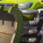
Figure 8 shows “beauty shots” of two of the characters from ‘Cars’. These images demonstrate ray traced reflections, shadows, and ambient occlusion.
图8展示了电影中的两个角色的渲染结果。这些图片展示了光线追踪、反射、阴影、环境OCC。
For convex surfaces like a car body, distant reflections do not need to be very accurate. In many shots, the maximum distance that a ray can hit geometry was set to 12 meters. If the ray didn’t hit anything within that distance, it would use a single held environment map instead.
对于突起的表面,例如一辆车的主题,远距离的反射不需要非常精确。在许多镜头中,一个光线可以碰到模型的最大距离设定为12m。如果光线在这个距离内没有碰到任何物体,它将会使用一个单独的环境贴图代替。
The reflections in the movie were usually limited to a single level of reflection. There were only a few shots with two levels of reflection, they are close-ups of chrome parts that needed to reflect themselves multiple times. Figure 9 shows an example.
在电影中的反射都是一次反射级别。只有极个别非常靠近摄像机的镜头需要两次反射,并且自身间的相互反射等。图9就是这样一个例子。
Figure 9: Chrome bumper with two levels of ray-traced reflection.
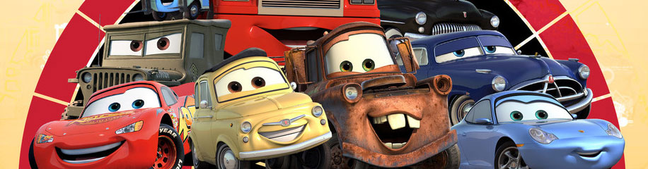
Figure 10 shows all the main characters in the ‘Cars’ movie. This is an example of a very complex scene with many shiny cars. The shiny cars reflect other cars, as shown in the three close-ups. The image also shows ray-traced shadows and ambient occlusion.
图10展示了这部电影中的主要角色。这个场景是一个带有很多闪耀的车的复杂场景。闪耀的车反射其他的车,比如特写镜头。这张图片还展示了光线追踪的阴影和环境OCC。

10 CONCLUSION
PRMan uses the REYES algorithm for rendering directly visible objects, and offers on-demand ray tracing for reflections, shadows, ambient occlusion, etc. It uses a multi resolution geometry cache and a multi resolution texture cache, and uses ray differentials to select the appropriate resolutions. Due to the observation that coherent rays have narrow beams while incoherent rays have wide beams, the method is efficient for ray tracing of complex scenes. The ray tracing functionality has been used for several movies, including Pixar’s ‘Cars’.
10 总结
PRMan使用REYES算法来渲染可直接被看到的模型,并且提供了符合需求的光线追踪来得到反射、阴影、环境OCC等等。它使用多种精度的物体缓存和多种精度的材质缓存,并且使用光线微积分来选择适合的精度。由于发现了连续的光线对应窄的光柱,不连续的光线对应宽的光柱,这个发现对复杂的场景的光线追踪是非常高效的。光线追踪的功能被反复用到了多部电影中,包括“汽车总动员”。
Acknowledgements
We would like to thank our colleagues in Pixar’s RenderMan Products group for providing an inspiring and creative environment and for many helpful discussions. Loren Carpenter implemented most of the SIMD speedups and Brian Smits helped us optimize other aspects of the ray-tracing efficiency. Tony Apodaca headed the Cars
“Nitro” speed team. Erik Smitt clarified some of the movie production details.
All images from ‘Cars’ are copyright c Disney Enterprises, Inc. and Pixar Animation Studios.
REFERENCES
[1] Anthony A. Apodaca and Larry Gritz. Advanced RenderMan — Creating CGI for Motion Pictures. Morgan Kaufmann,
2000.
[2] Per H. Christensen. Point clouds and brick maps for movie production. InMarkus Gross and Hanspeter Pfister, editors,
Point-Based Graphics, chapter 8.4. Morgan Kaufmann, 2006. (In press).
[3] Per H. Christensen, David M. Laur, Julian Fong, Wayne L. Wooten, and Dana Batali. Ray differentials and multiresolution
geometry caching for distribution ray tracing in complex scenes. Computer Graphics Forum (Proceedings of
Eurographics 2003), 22(3):543–552, 2003.
[4] Robert L. Cook, Loren Carpenter, and Edwin Catmull. The Reyes image rendering architecture. Computer Graphics
(Proceedings of SIGGRAPH ’87), 21(4):95–102, 1987.
[5] Larry Gritz and James K. Hahn. BMRT: A global illumination implementation of the RenderMan standard. Journal of
Graphics Tools, 1(3):29–47, 1996.
[6] Homan Igehy. Tracing ray differentials. Computer Graphics (Proceedings of SIGGRAPH ’99), pages 179–186, 1999.
[7] Toshiaki Kato. The Kilauea massively parallel ray tracer. In Alan Chalmers, Timothy Davis, and Erik Reinhard, editors,
Practical Parallel Rendering, chapter 8. A K Peters, 2002.
[8] Timothy L. Kay and James Kajiya. Ray tracing complex scenes. Computer Graphics (Proceedings of SIGGRAPH ’86),
20(4):269–278, 1986.
[9] Hayden Landis. Production-ready global illumination. In SIGGRAPH 2002 course note #16, pages 87–102, 2002.
[10] Matt Pharr, Craig Kolb, Reid Gershbein, and Pat Hanrahan. Rendering complex scenes with memory-coherent ray
tracing. Computer Graphics (Proceedings of SIGGRAPH ’97), pages 101–108, 1997.
[11] William T. Reeves, David H. Salesin, and Robert L. Cook. Rendering antialiased shadows with depth maps. Computer
Graphics (Proceedings of SIGGRAPH ’87), 21(4):283–291, 1987.
[12] Brian Smits, Peter Shirley, andMichaelM. Stark. Direct ray tracing of displacement mapped triangles. In Rendering
Techniques 2000 (Proceedings of the 11th Eurographics Workshop on Rendering), pages 307–318, 2000.
[13] Gordon Stoll,William R. Mark, Peter Djeu, RuiWang, and Ikrima Elhassan. Razor: an architecture for dynamic
multiresolution ray tracing. Technical Report TR-06-21, University of Texas at Austin, 2006.
[14] Frank Suykens and Yves D. Willems. Path differentials and applications. In Rendering Techniques 2001 (Proceedings of
the 12th Eurographics Workshop on Rendering), pages 257–268, 2001.
[15] Ingo Wald, Andreas Dietrich, and Philipp Slusallek. An interactive out-of-core rendering framework for visualizing
massively complex models. In Rendering Techniques 2004 (Proceedings of the Eurographics Symposium on Rendering
2004), pages 81–92, 2004.
[16] Ingo Wald, Philipp Slusallek, Carsten Benthin, and Michael Wagner. Interactive rendering with coherent raytracing.
Computer Graphics Forum (Proceedings of Eurographics 2001), 20(3):153–164, 2001.
[17] Lance Williams. Pyramidal parametrics. Computer Graphics (Proceedings of SIGGRAPH ’83), 17(3):1–11, 1983.
[18] Sung-Eui Yoon, Christian Lauterbach, and Dinesh Manocha. RLODs: Fast LOD-based ray tracing of massive models. In
Proceedings of Pacific Graphics ’06, 2006.
[19] Sergei Zhukov, Andrei Iones, and Gregorij Kronin. An ambient light illumination model. In Rendering Techniques ’98
(Proceedings of the 9th Eurographics Workshop on Rendering), pages 45–55, 1998.


推荐相关中文教程

VUE自然景观实战案例教程
本套教学是由MG录制。讲解分析了vue的海水材质问题,以及全中国首次以案例的形式讲解vue与maya的结合运用,如何将maya的角色动画导入到vue场景文件中做遮罩并且渲染。Substance Designer贴图材质系统完全教学
本套Substance Designer教材是由AboutCG陶仁贤历经三个月的潜心研究,录制完成。从Substance Designer在游戏行业的流程入手,逐一介绍产品特点,界面,以及内置的200多个节点的原理和结构。并通过多个实例教材为您展示从零开始制作贴图,Substance Designer与Maya Anrold渲染引擎的互动,Substance Designer与Max互动、Substance Designer与Unity 3D引擎互动、Substance Designer与UnrealEngine3/UDK互动。arnold for maya渲染器完全教学
Arnold渲染器是基于物理算法的电影级别渲染器,正在被越来越多的好莱坞电影公司以及工作是作为首席渲染器使用。与传统用于CG动画的Scanline(线扫描)渲染器(Renderman)不同,Aronld是照片真实,基于物理的光线追踪渲染器。MAXWELL RENDER从入门到精通教学
Maxwell Render 是一款可以不依附其他三维软件可以独立运行的渲染软件,采用了光谱的计算原理,打破了长久以来光能传递等渲染技术,使结果更逼真。Maxwell是一个基于真实光线物理特性的全新渲染引擎,按照完全精确的算法和公式来重现光线的行为。

推荐课程


推荐教程
这篇文章内容十足啊!